

Technical Articles
Generator, Voltage Regulator & Cut Out
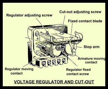
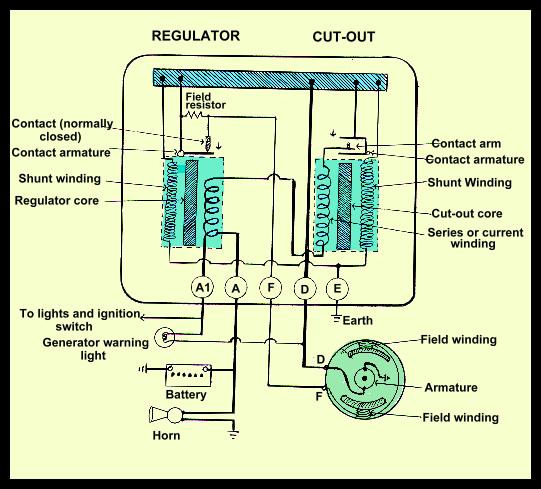
Owning a Morry seems to involve a never ending series of repair jobs to keep the old car going. On the way home from the Geelong camel races I noticed that the headlights of "Grommet" seemed more yellow than normal. A quick check of the battery showed that it was almost flat. One more thing had gone wrong with my Morry! I decided to try and repair the fault myself and in the process learn how the electrical system works. These notes are the result of my research into the secrets of how generators and regulators work.
Testing the Regulator and Cut-out.
The regulator can be checked without removing it from the car. The wires are removed from terminals 'A' and 'A1' and connected together - this simply enables the engine to be run by supplying power from the battery whilst isolating the generator and regulator from the car accessories and battery. A voltmeter is connected to terminal 'D' and 'E'. The engine speed is increased slowly until the needle flicks and then steadies. This should occur at about 16 volts (refer to the manual for the actual voltage as it is temperature dependant). What this test does is measure the voltage output of the generator when it is just sufficient to operate the voltage regulator when the system is not under load. The test is made when the voltage winding is cold and must be completed within 30 seconds. This tested okay in the case of "Grommet". As a matter of interest Bosch regulators are measured when the system is at full operating temperature!
The cut-out is checked by measuring the voltage at 'D' when the contacts close. It should be about 13 volts. Gromet's cut-out setting was fine!
Finally, I removed the control box from the car and tested it with a variable voltage supply. I connected a 12V 5W globe between terminals 'F' and 'D', a voltmeter between 'A' and 'E' and the variable power supply between 'D' and 'E'. As the voltage increased so did the light from the globe. A sudden change of the light from the globe to a dull glow indicated that the voltage regulator contacts had opened and the power was flowing through the resistor. This occurred at 16.2 volts which was within specification.
I could only conclude that the generator was faulty - but the fault was only evident when heavy currents were flowing. So I again checked the generator output with all lights on by connecting a wire between terminal 'F' and 'D' and measuring the voltage at 'D'. The test allowed the generator to run at maximum output without any voltage or current regulation. It showed that the voltage output was barely 11 volts proving a crook generator. The good book recommended cleaning the generator commutator with petrol and carefully polishing with fine glass paper. A nicely polished commutator and new brushes seemed to cure the fault.
Reconditioning old Control Boxes.
Whilst I was playing with the control box from "Grommet", I decided to try and restore an old one from my box full of spares. The Morris Minor Workshop Manual recommends that you clean the regulator contacts with emery cloth or a fine carborundum stone. The cut-out points should be cleaned with fine glass paper. On the other hand, Bosch recommends that the contact points should only be cleaned with a fine file as dirt left behind after cleaning with an abrasive paper will cause burning.
The only description I could find on removing the points, cleaning and resetting the points came from the official BC Morris Major Workshop Manual. I don't intend to explain the procedure as it is lengthy but it is certainly not a difficult task for the DIY mechanic. The only difficulty for most people would be to obtain an accurate volt meter. I found that digital voltmeters were not satisfactory when testing the control box in the car as, when set to the DC range, they appeared to have a very fast sampling time and gave wildly fluctuating results. This was probably due to "noise" induced by the commutator and voltage regulator contacts. However, if the regulator/cut-out is removed from the car and adjusted using a variable voltage supply; a digital meter is ideal to measure the voltages.
Three Bobbin Regulators.
The two bobbin control box as fitted to the Morris Minor has a distinct disadvantage compared with a three bobbin box. The three bobbin control box has separate bobbins for regulating the voltage and current; the third bobbin operates the cut-out switch.
With a two bobbin control box, as you adjust the voltage regulator you are also altering the current limit cut-out. It is therefore more difficult (impossible!) to adjust the setting so that both the voltage and current setting are optimised. In other words, the setting is a compromise. A three bobbin control box, with separate bobbins for voltage and current regulation, does not suffer from this fault. Apparently, BMC continued to use the two bobbin control box to save the additional cost of fitting three bobbins boxes.
A design fault of the Morris Minor that can cause the generator to burn out should be mentioned. The 'E' or earth terminal of the control box also connects to the earth terminals of the windscreen wiper motor and the interior lamp. If the earth 'E' on the control box becomes disconnected from the chassis and the interior light or wiper motor is left on (with the engine not running), it is possible for current to pass through the shunt winding of the cut-out in the reverse direction causing the cut-out points to close. This will cause current to flow from the battery through the generator and burn out the armature winding. If you are restoring a Morris Minor it is a good idea to change the wiring so that the interior light and windscreen wiper motor have separate earth's to the control box. Better still, fit an alternator to the engine!
Using an Alternator.
If your car has a lot of electrical gadgets and widgets consuming heaps of electrical power, then seriously consider swapping the generator for an alternator.
The generator cannot cope with the modern heavy electrical demands of modern cars. The output is too low, it can only operate in one direction, the high centrifugal forces acting on the rotating armature windings prevent high speed operation and commutation is not completely reliable when heavy currents are generated.
In contrast the alternator is light and has a high output, can operate in either direction, can operate at very high speeds and the brushes only carry a very small current to the field windings.
The alternator is able to achieve these excellent characteristics because the heavy rotating armature winding of a generator is replaced by a fixed armature winding in the alternator. It uses a rotating magnetic field in an assembly called a rotor and a fixed armature winding called the stator windings. The rotor assembly is light and designed to rotate at high speeds. The alternator produces only alternating current which must be rectified to direct current. This is accomplished by the use of solid state diodes. With a higher crankshaft pulley ratio, the alternator can be driven at a speed sufficient to charge the battery when the engine is idling and yet continue to operate with complete safety at maximum engine rpm.
